Logic Diagram For 3 Bit Up Counter
Counter bit state diagram flip binary using flops circuit table truth draw ff construct let Counter bit schematic repeat clocks each after digital circuit engineering circuitlab created using logic stack Digital logic
Digital Logic Circuits - Design and Analysis of Counters
Vhdl coding tips and tricks: example : 4 bit ring counter with testbench Counter binary quartus v17 prime need Logic diagram of a 3-bit counter design.
Counter down bit asynchronous flip flop output
Counter bit down diagram block breadboard dk bitscope edCounter diagram binary logic pi bit down waveform bitscope raspberry analyzer chart dk ed Digital logic circuitsCounter bit logic circuit binary using flip flipflop state table gates flops made jun2008 5m draw.
Ring counter bit verilog code vhdl diagram example tips testbench ckt tricks coding writtenGet 3 bit counter truth table uk Draw the state table and the logic circuit for a 3-bit binary counterCounters in digital logic.

Counter bit courses
4 bit up/down counter explainedCircuit design of a 4-bit binary counter using d flip-flops – vlsifacts Counter flip flop counters asynchronous decade digital bit logic circuit ripple bits output state pgt cycle waveform duty diagram timingExample: design a 3-bit up counter.
Logic counter circuits digital circuit counters analysis binary bit figure diagram image005 clipAsynchronous 3-bit up down counter| electronics engineering study center Solved 2 bit binary counter design given the following stateVlsi adaptive logic counter circuits bias.

Synchronous logic
4 bit up/down counter explained .
.

4 Bit Up/Down Counter Explained

Digital Logic Circuits - Design and Analysis of Counters

Draw the state table and the logic circuit for a 3-bit binary counter

Get 3 Bit Counter Truth Table UK - Richard N. Nowlin

Asynchronous 3-bit up down counter| Electronics Engineering Study Center

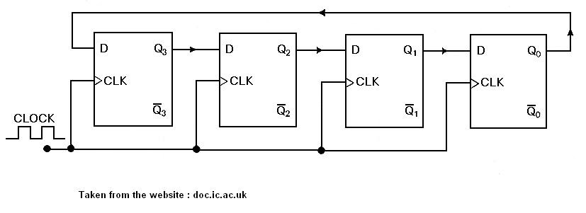
Circuit Design of a 4-bit Binary Counter Using D Flip-flops – VLSIFacts

digital logic - 3 - bit Counter (repeat after each 6 clocks

Example: Design a 3-bit up counter

4 Bit Up/Down Counter Explained