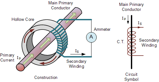
Ct Circuit Diagram
Ct secondary equivalent circuit diagram Ct wiring diagram Equivalent secondary
CT Wiring Question - Electric motors & generators engineering - Eng-Tips
Ct vt connection pt sld line electrical load system current voltage comparison source Ct circuit secondary equivalent diagram principle low implementation analyzer basis pressure test Current ct transformer working principle construction circuit symbol primary bar connected
Ct cores primary circuit connection diagram
Circuit coresCurrent transformers (ct) Current transformer installation for three phase power supply- ct coilSensor circuit current ct transformer schematic output varies practical testing changes flow shows below much.
Current transformer sensor circuitCt wiring diagram tips question failed ways found ve just Current ct transformersTransformer circuit ct circuitglobe secondary linquip phasor.

Digital ammeter wiring with current transformer
What is current transformer (ct)? definition, construction, phasorCt wiring question Ammeter wiring transformer current digital ct diagram coil transformers wire electrical electricalonline4u connections(pdf) design and implementation of the ct analyzer on the basis of the.
Current transformer wiring installation ct diagram phase coil three power electrical supply coilsCurrent transformer (ct) Electrical systems: ct and vt comparison and connectionVt voltages wiring cr4 circuits.

Ct wiring diagram
High voltages seen on ct's .
.

Digital Ammeter Wiring With Current Transformer - CT Coil

What is Current Transformer (CT)? Definition, Construction, Phasor

Current Transformer (CT) - Construction and Working Principle

(PDF) Design and Implementation of the CT Analyzer on the Basis of the

CT Wiring Question - Electric motors & generators engineering - Eng-Tips

Ct Wiring Diagram - Wiring Diagram

Current Transformers (CT) - YouTube

Current Transformer Sensor Circuit
Ct Wiring Diagram